Conductor Casing: Technical Guide for OCTG Casing and Tubing Buyers

Conductor casing is the first and largest casing string installed in a well, isolating loose surface formations and providing structural support for subsequent casing strings. BSCO explains conductor casing functions, drilling use, installation, sizes, specs, diagrams, and applications.
What Is Conductor Casing?
Definition of Conductor Casing
Conductor casing is the outermost, shallowest string in a well, set before main drilling begins. Distinct from offshore drive pipe, it is typically low-carbon steel line pipe (API 5L X56, BTC) or heavy-wall OCTG.
Conductor casing key specifications: OD range 16 inches to 36 inches. Typical set depth 60 to 150 feet onshore. Common material is API 5L X56 low-carbon steel line pipe with BTC (buttress thread) connections or heavy-wall OCTG. The conductor casing is cemented into shallow unconsolidated soil and supports the wellhead and all inner casing strings including surface casing, production casing, and tubing.
Where It Sits in the Casing Program
The well conductor casing is always the first string installed — the starting point of a casing program that builds inward: conductor → surface → intermediate → production casing, with tubing run inside the innermost string.
Casing program installation order: 1. Conductor casing (60–150 ft, OD 20–36 inches) — the first string installed. 2. Surface casing (500–3,000 ft, OD 13-3/8 to 20 inches). 3. Intermediate casing (3,000–10,000 ft, OD 9-5/8 to 13-3/8 inches) — used if needed. 4. Production casing (6,000–18,000+ ft, OD 5-1/2 to 9-5/8 inches). 5. Tubing (near total depth, OD 2-3/8 to 4-1/2 inches) — the hydrocarbon flow path. Each string is nested inside the previous one at increasing depth.
Function and Purpose of Conductor Casing
Primary Functions of Conductor Casing
Prevent Borehole Collapse
Stabilizes shallow unconsolidated formations — sand, gravel, and weak soil — that would otherwise cave into the borehole and block drilling progress before deeper casing can be set.
Support the Wellhead & BOP Stack
Provides the structural foundation for the wellhead assembly and blowout preventer (BOP) stack — the critical surface equipment that controls well pressure throughout drilling and completion.
Protect Freshwater Aquifers
Isolates shallow freshwater-bearing zones from drilling fluids and wellbore contaminants, ensuring compliance with environmental regulations and safeguarding groundwater resources.
Enable Drilling Fluid Returns
Acts as a conduit for drilling returns — mud and cuttings — to flow back to the surface in a controlled manner, especially on land wells where the conductor provides the initial return flow path before the surface casing is in place.
Contain Shallow Gas Kicks
Provides the first line of defense against unexpected shallow gas influx, allowing the diverter system to be installed and enabling the rig crew to safely redirect gas away from the rig floor during initial drilling operations.
Why It Is the First Casing String Run
It is run first because conductor casing creates the well’s structural foundation and acts as an initial safety barrier before deeper drilling begins. Onshore, it is typically set at 50–500 ft (15–150 m), while offshore wells often require greater depths.
Conductor Casing in Drilling and Well Construction
Role During Spudding
The spud is the very first moment a drill bit touches the ground — and the conductor casing in drilling operations is what makes it possible. Already set in place, the conductor gives the bit a stable, guided entry into the formation and keeps the shallow borehole from caving in before surface casing can be run.
-
Conductor Is Set First Driven or drilled and cemented to 60–150 ft before the rig is fully rigged up — this is the anchor for everything that follows.
-
Drill Bit Enters Inside the Conductor When spudding begins, the bit drills downward through the conductor bore, which acts as a guide sleeve to keep the hole straight and on-target.
-
Borehole Stays Open The conductor walls hold back loose sand and gravel, preventing collapse and allowing mud circulation to start from the very first meter.
-
Wellhead Lands on Top The wellhead housing is installed on the conductor, creating the surface control point for all subsequent casing strings and pressure equipment.
During spudding, the drill bit enters the ground through the conductor casing bore. Drilling mud flows down through the drill pipe and returns up through the annulus between the drill pipe and conductor casing walls, carrying cuttings to the surface. The conductor keeps the shallow borehole open in unconsolidated soil.
Interaction with Drilling Fluids and Returns
During top-hole drilling, the conductor casing is the only barrier between the wellbore and the surrounding formation. It channels drilling mud and cuttings back to the surface in a controlled loop — and on higher-risk wells, it is where the diverter system connects to redirect flow if shallow gas is encountered.
Mud Circulation Loop
Drilling mud is pumped down through the drill string, exits the bit, and returns upward through the annulus between the drill pipe and conductor wall — carrying rock cuttings to surface.
Hydrostatic Pressure Control
The mud column inside the conductor applies hydrostatic pressure on the formation face, preventing fluid influx from shallow permeable zones while the top-hole section is drilled.
Cuttings Transport to Surface
The conductor annulus must be sized to allow sufficient fluid velocity for efficient cuttings transport. Too large a gap slows velocity; too narrow restricts flow and increases pump pressure.
Diverter System Tie-In
On offshore rigs and high-risk land wells, a diverter is installed on top of the conductor. If shallow gas enters the wellbore, the diverter seals around the drill pipe and routes the gas overboard or to a safe flare — protecting the rig crew.
During top-hole drilling, the conductor casing channels drilling mud and cuttings back to the surface. Mud is pumped down through the drill string, exits the bit, and returns upward through the annulus between drill pipe and conductor wall carrying rock cuttings. On offshore and high-risk land wells, a diverter system is installed on top of the conductor to redirect shallow gas away from the rig floor through a vent line.
Installation Methods of Conductor Casing
Driving / Pile-Driving
The simplest and fastest installation method. A diesel or hydraulic pile hammer sits on top of the conductor pipe and drives it into the ground with repeated blows — much like driving a fence post, but at industrial scale. No drilling or cementing is required, making this the most cost-effective option for shallow wells in firm soil.
The hammer strikes a drive head that distributes the impact evenly across the pipe’s top edge. Blow count per foot is monitored to confirm the conductor reaches competent formation and achieves adequate bearing capacity to support the wellhead and BOP.
- EquipmentDiesel or hydraulic pile hammer
- CementingNot required
- SpeedFast — often completed in hours
- Best ForOnshore wells, firm or stiff soil
Drilling and Cementing
The most widely used method across both onshore and offshore operations. A hole is drilled to the target setting depth using a smaller pilot bit or large-diameter hole opener, then the conductor casing is lowered in and cemented in place — creating a permanent bond between the pipe and the surrounding formation.
Cementing can be done in two ways. Top-up cementing is simpler: cement is pumped down the annulus from the surface and allowed to fill upward. Inner-string cementing uses a small-diameter stinger run inside the casing to pump cement through the shoe and up the annulus — giving better control of placement, especially on deeper conductors where top-up cement may not reach the shoe evenly.
- EquipmentDrill bit + cement unit
- CementingRequired — top-up or inner string
- SpeedModerate — 1–2 days typical
- Best ForMost well types; any formation
Jetting (Offshore / Soft Seabed)
In deepwater and soft-seabed locations, jetting conductor casing is the standard method where pile-driving is impractical. High-pressure drilling mud is pumped down through the drill string and out jet nozzles at the casing shoe, washing away soft sediment and allowing the conductor to sink under its own weight and the weight of the drill string above it.
Once the conductor reaches the target penetration depth, the pumps are stopped and the surrounding sediment reconsolidates around the pipe, providing friction-based support. In some cases, cement is pumped afterward to improve the bond. This method is standard for deepwater subsea wells where the seabed consists of soft clay and silt.
- EquipmentMud pumps + jet shoe
- CementingOptional — often not needed
- SpeedModerate — depends on seabed hardness
- Best ForDeepwater subsea wells, soft clay seabed
| Factor | Pile-Driving | Drill & Cement | Jetting |
|---|---|---|---|
| Environment | Onshore | Onshore & offshore | Offshore / deepwater |
| Formation Type | Firm soil, clay, packed gravel | Any — soft to hard | Soft seabed sediment (clay, silt) |
| Cement Required | No | Yes — top-up or inner string | Optional |
| Typical Depth | 40–150 ft | 60–500+ ft | 50–300 ft below mudline |
| Speed | Fastest (hours) | Moderate (1–2 days) | Moderate (variable) |
| Relative Cost | Lowest | Moderate | High (deepwater spread) |
Conductor casing installation method comparison: Pile-driving uses a diesel or hydraulic hammer to drive the casing into firm soil onshore at 40–150 ft, no cement required, fastest and lowest cost. Drilling and cementing involves drilling a hole, running casing, and cementing in place using top-up or inner-string methods, suitable for any formation onshore or offshore at 60–500+ ft, moderate speed and cost. Jetting uses high-pressure mud to wash the casing into soft seabed sediment at 50–300 ft below mudline on deepwater wells, cement is optional, moderate speed but higher cost due to deepwater rig spread.
Conductor Casing Size, Diameter, ID, Depth and Length
Common Outside Diameters
| Nominal OD | Typical Wall (in) | Approx. ID (in) | Common Grade | Typical Use |
| 20″ | 0.500 – 0.750 | 18.5 – 19.0 | API 5L X52 / B | Onshore deep wells |
| 24″ | 0.500 – 1.000 | 22.0 – 23.0 | API 5L X52 / B | Onshore / shallow offshore |
| 26″ | 0.625 – 1.000 | 24.0 – 24.75 | API 5L X52 | Offshore platforms |
| 30″ | 0.750 – 1.250 | 27.5 – 28.5 | API 5L X56 / X65 | Offshore structural |
| 36″ | 1.000 – 1.500 | 33.0 – 34.0 | API 5L X65 / X70 | Deepwater subsea |
Wall Thickness and Inside Diameter (ID)
Quick Calculator
Calculated Specifications
Weight
—
lb/ft
Weight
—
kg/m
Approx. ID
—
inches
Nominal OD
—
Wall Thickness
—
Common Grade
—
Typical Use
—
Formula:
W (lb/ft) = 10.6906 × (OD − WT) × WT | W (kg/m) = W (lb/ft) × 1.4882
Request a Quote
Pre-filled with your selected specs — opens your email client.
Typical Setting Depth and Length
Typical conductor casing setting depth is 50–300 ft onshore and about 200–500 ft below mudline offshore, depending on soil strength and well design. Pipe is commonly supplied in R3 length, about 34–48 ft (10.36–14.63 m) per joint.
Specifications and Common Sizes of Conductor Casing Pipe
Material Standards
API 5L conductor casing is commonly supplied as seamless or welded line pipe in PSL1
| API 5L Grade | Typical Chemical Composition, PSL1 Max. (%) | Minimum Yield Strength | Minimum Tensile Strength | Typical Cost Level |
| Grade B | C ≤0.28, Mn ≤1.20, P ≤0.030, S ≤0.030 | 241–245 MPa | 414–415 MPa | Low |
| X42 | C ≤0.28, Mn ≤1.30, P ≤0.030, S ≤0.030 | 290 MPa | 414–415 MPa | Low–Medium |
| X52 | C ≤0.28, Mn ≤1.40, P ≤0.030, S ≤0.030 | 359–360 MPa | 455–460 MPa | Medium |
| X56 | C ≤0.28, Mn ≤1.40, P ≤0.030, S ≤0.030 | 386–390 MPa | 490 MPa | Medium–High |
| X60 | C ≤0.28, Mn ≤1.40, P ≤0.030, S ≤0.030 | 414–415 MPa | 517–520 MPa | High |
| X65 | C ≤0.28, Mn ≤1.40, P ≤0.030, S ≤0.030 | 448–450 MPa | 531–535 MPa | High–Very High |
Connections: Welded vs. Threaded
| Connection Type | Best For | Advantages | Limitations | Cost Level |
| Welded / Plain End | Large-diameter conductor casing, offshore wells, driven installation, and projects requiring high structural support | Good structural continuity, no coupling protrusion on the outside diameter, suitable for large OD and heavy-load conditions; material cost is usually lower | Field welding takes longer and requires qualified welders, WPS/PQR, and NDT inspection; weather and site conditions can affect installation | Lower pipe cost, medium–high installation cost |
| Threaded / Coupled or Special Connector | Onshore wells, HDD projects, shallow wells, no-hot-work environments, or projects requiring shorter rig time | Fast make-up, no field welding required, and more controllable connection quality; special threaded connectors can also be used for conductor driving | Connector or coupling cost is higher, and the outside diameter may increase; standard threaded & coupled connections may be limited by coupling strength or potential leak paths | Higher pipe/connector cost, lower installation time |
For large-diameter, offshore, driven or high-structural-load conductor casing, choose welded plain-end pipe or engineered welded-on connectors. For projects prioritizing fast installation, no hot work, repeatable makeup, or limited welding access, choose threaded or special connector conductor casing.
Size-Specific Specifications
Common conductor casing sizes range from 20″ to 36″ OD. Each size serves a different well type and operating environment. Click any card to send an inquiry with that specification pre-filled.
20″
OD (508 mm)
Onshore Deep Wells
The smallest common conductor size. Used on onshore wells in stable formations where a compact casing program allows a smaller starting diameter. Suitable for wells that begin with a 17-1/2″ surface hole section.
- Wall Thickness0.500″ – 0.750″
- Weight Range104 – 154 lb/ft
- Approx. ID18.5″ – 19.0″
- Common GradeAPI 5L X52 / B
Click to Inquire
24″
OD (610 mm)
Onshore / Shallow Offshore
The most versatile conductor size, widely used across onshore and shallow-water offshore wells. Pairs with a 17-1/2″ hole and accepts 20″ or 18-5/8″ surface casing inside, offering flexibility for a range of well designs.
- Wall Thickness0.500″ – 1.000″
- Weight Range126 – 246 lb/ft
- Approx. ID22.0″ – 23.0″
- Common GradeAPI 5L X52 / B
Click to Inquire
26″
OD (660 mm)
Offshore Platforms
Common on fixed offshore platforms and jack-up rigs. Provides the clearance needed for 20″ surface casing below, and the wall thickness to handle wave loading and platform structural stresses in shallow to mid-water depths.
- Wall Thickness0.625″ – 1.000″
- Weight Range170 – 267 lb/ft
- Approx. ID24.0″ – 24.75″
- Common GradeAPI 5L X52
Click to Inquire
30″
OD (762 mm)
Offshore Structural
A heavy-duty offshore conductor designed to serve as both a well conduit and structural member on platform wells. Higher-grade steels (X56/X65) are specified to resist the combined loads of wave action, current forces, and the weight of the casing strings hung below.
- Wall Thickness0.750″ – 1.250″
- Weight Range234 – 385 lb/ft
- Approx. ID27.5″ – 28.5″
- Common GradeAPI 5L X56 / X65
Click to Inquire
36″
OD (914 mm)
Deepwater Subsea
The largest standard conductor, used on deepwater subsea wells where the conductor is jetted into the seabed and must support a tall subsea wellhead stack. The heaviest wall thicknesses (up to 1.500″) and highest grades (X65/X70) provide the axial capacity to support all inner strings in deep water.
- Wall Thickness1.000″ – 1.500″
- Weight Range374 – 553 lb/ft
- Approx. ID33.0″ – 34.0″
- Common GradeAPI 5L X65 / X70
Click to Inquire
Conductor Casing vs. Surface Casing

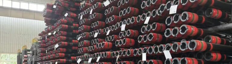
30 Inch Conductor Casing with BTC End
| Attribute | Conductor Casing | Surface Casing |
| Position | Outermost / first string | Inside conductor |
| Typical OD | 20″ – 36″ | 9-5/8″ – 20″ |
| Setting Depth | 50 – 500 ft (onshore) | 500 – 2,500 ft |
| Primary Function | Structural support, surface stability | Aquifer isolation, BOP anchor |
| Common Standard | API 5L line pipe | API 5CT OCTG |
| Installation | Driven / drilled+cemented / jetted | Drilled and cemented |
Buyer Summary
Conductor casing is the foundation of every well. BSCO is a China-based supplier with 20+ years of experience. Explore our 20″, 30″, and 36″ casing or contact us for the latest price.
Frequently Asked Questions (FAQs)
Conductor casing is the first and largest-diameter casing string run into a well. It is installed before deep drilling begins and isolates loose near-surface formations, supports the wellhead and BOP stack, and provides a stable foundation for all subsequent casing strings.
Its main functions are to prevent collapse of unconsolidated surface soils, isolate shallow aquifers from drilling fluids, provide structural support for the wellhead and surface equipment, and serve as a return path for drilling mud during top-hole drilling operations.
Typical outside diameters range from 13-3/8″ up to 36″. Onshore wells commonly use 20″ or 24″; offshore platforms favor 26″ or 30″; deepwater subsea wells often require 36″. Wall thickness ranges from 0.500″ to 1.500″ depending on load and depth.
Three methods are common: pile-driving (hammered into firm soil), drilling and cementing (most common onshore), and jetting (washing the pipe into soft seabed sediments — standard for deepwater subsea wells). The choice depends on formation strength and water depth.
Conductor casing is the outermost, shallowest string (20″–36″, set at 50–500 ft) providing structural support. Surface casing is run inside the conductor (9-5/8″–20″, set at 500–2,500 ft) and seals off freshwater aquifers while anchoring the BOP. Conductor is typically API 5L; surface casing is typically API 5CT OCTG.
Most conductor casing is supplied as API 5L line pipe (Grade B through X70), not strictly OCTG. However, heavy-wall and high-load applications — particularly for deepwater wells — may use API 5CT OCTG materials. Buyers should confirm the required standard with the well design engineer before ordering.
Reference Sources
- Organization: American Petroleum Institute (API)
- Type: Industry Standard / Specification
- Publication Year: Latest official standard page
- Citation Token: (API 5L)
- Nofollow Link: https://www.api.org/products-and-services/standards/important-standards-announcements/standard-5l
- Organization: Electronic Code of Federal Regulations (eCFR)
- Type: Federal Regulation
- Publication Year: Current version
- Citation Token: (eCFR, 30 CFR Part 250)
- Nofollow Link: https://www.ecfr.gov/current/title-30/chapter-II/subchapter-B/part-250/subpart-D/subject-group-ECFR1a08921df9e15a2
- Organization: International Association of Drilling Contractors (IADC)
- Type: Industry Glossary / Reference
- Publication Year: Current web reference
- Citation Token: (IADC Lexicon)
- Nofollow Link: https://iadclexicon.org/conductor-casing-or-conductor-pipe-floating-installations/
- Organization: Standards Norway / NORSOK
- Type: Industry Standard / Well Integrity Guideline
- Publication Year: Current standard reference
- Citation Token: (NORSOK D-010)
- Nofollow Link: https://standard.no/en/news/two-norsok-d-standards-are-revised-and-on-public-enquiry/